Gateway Deployment
Mount a wireless gateway on the EDC telescopic pole for cellular or Wi-Fi connectivity.
Overview
The EDC includes a carbon fiber telescopic pole and T-Bar mount system for deploying and elevating wireless gateways, access points, or other radio devices. This provides elevated positioning for cellular (5G/LTE) or Wi-Fi connectivity with improved coverage and signal aquisition.
Common Gateway Options:
- Mako Networks 5600 5G Security Gateway (default)
- HiveRadar 5G Standalone Cellular Wireless Gateway
- Wireless access points
- Other network or radio devices with appropriate mounting
Note: This guide provides the physical deployment procedure. User will customize based on specific gateway model and deployment requirements.
When to Deploy:
- After physical setup is complete (legs deployed, EDC positioned)
- Can be installed before or after powering on
- Standard part of most EDC deployments
Components Needed
Before starting, gather these components:
From EDC Storage:
- Carbon fiber pole (stored in top drawer)
- Carbon fiber extension pole (optional, stored in work surface lid)
- T-Bar bracket (stored in top storage shelf)
Your Wireless Device:
- Gateway or access point (e.g., Mako 5600, or your chosen device)
- Mounting bracket (device-specific, may be in accessory pouch such as Mako 5600 T-Bar bracket adaptor)
- Antennas (if applicable, install after mounting)
Optional:
- HiveRadar Beacon (stored in top shelf, for visual identification)
Step 1: Prepare the Pole
- Retrieve the carbon fiber pole from the top drawer
- Optional: Retrieve the extension pole from the work surface lid storage (only needed for additional height)
Reminder: All EDC drawers use twist-lock mechanisms (twist ~90° upward or downward to unlock). For detailed drawer operation, see Storage Drawers.
Step 2: Expose the Pole Mount
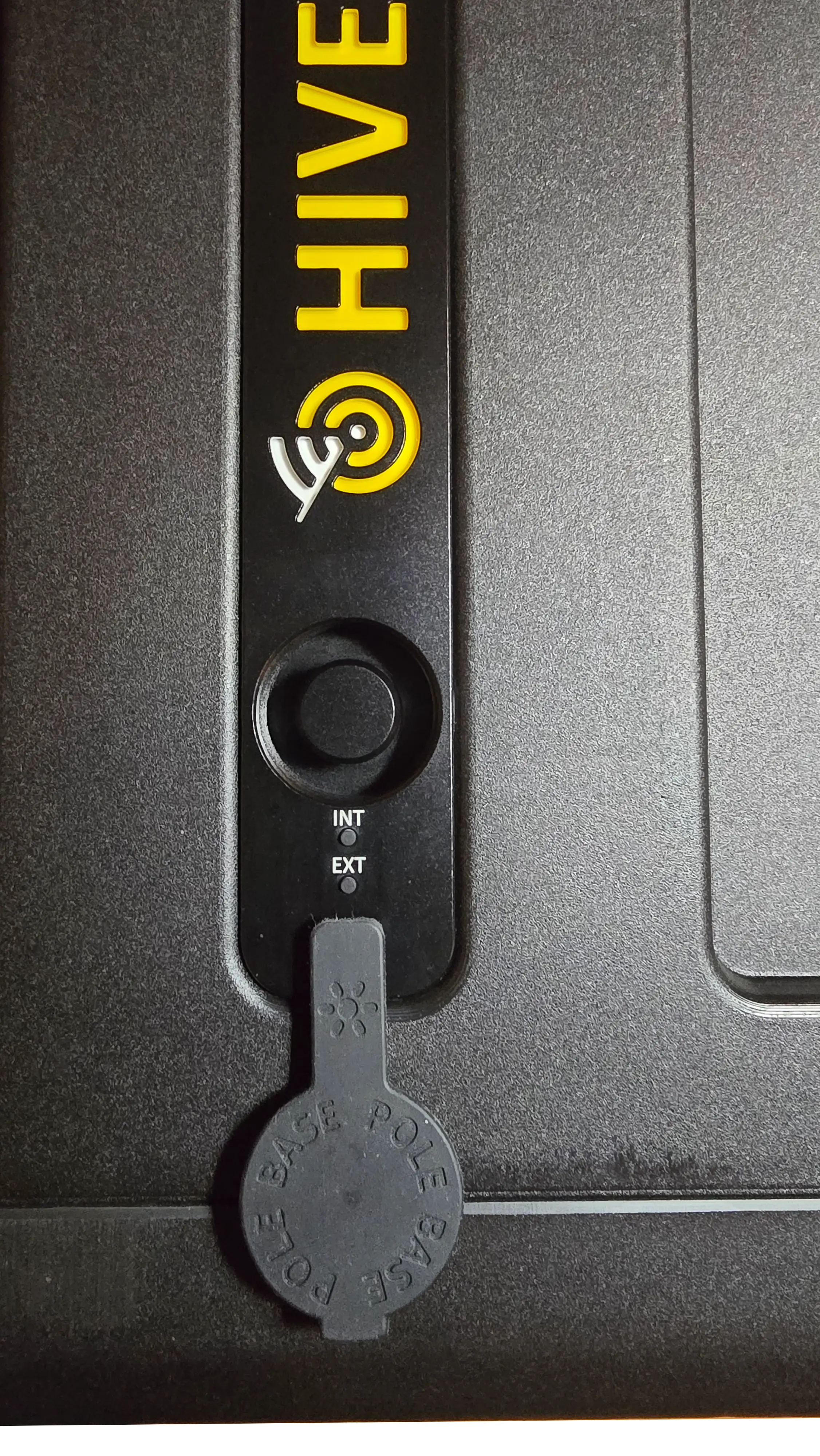
- Locate the pole mount on top of the deployed EDC (covered by a rubber protective cover)
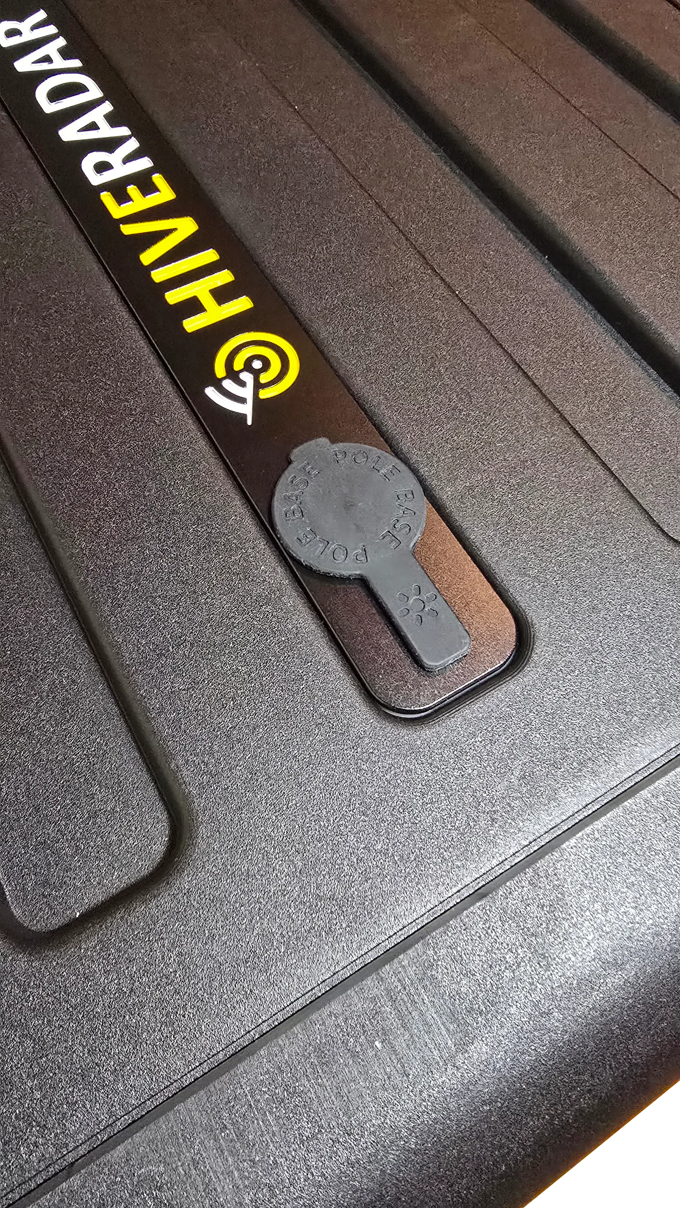
- Remove the rubber cover and set aside for later reinstallation
Step 3: Prepare the T-Bar Bracket
- Retrieve the T-Bar bracket from the top storage shelf
- Identify the T-Bar Components:
- T-Bar plate for mounting
- Threaded screw on top for Light Beacon mounting
- Orientation knob (for adjusting angle)
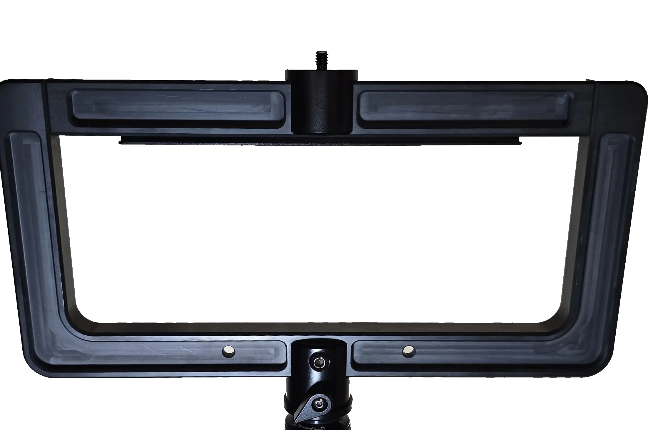
⚠️ Important: The orientation knob should only be loosened slightly - never completely unscrew it as it can fall off and become lost.
Step 4: Attach Gateway to T-Bar Bracket
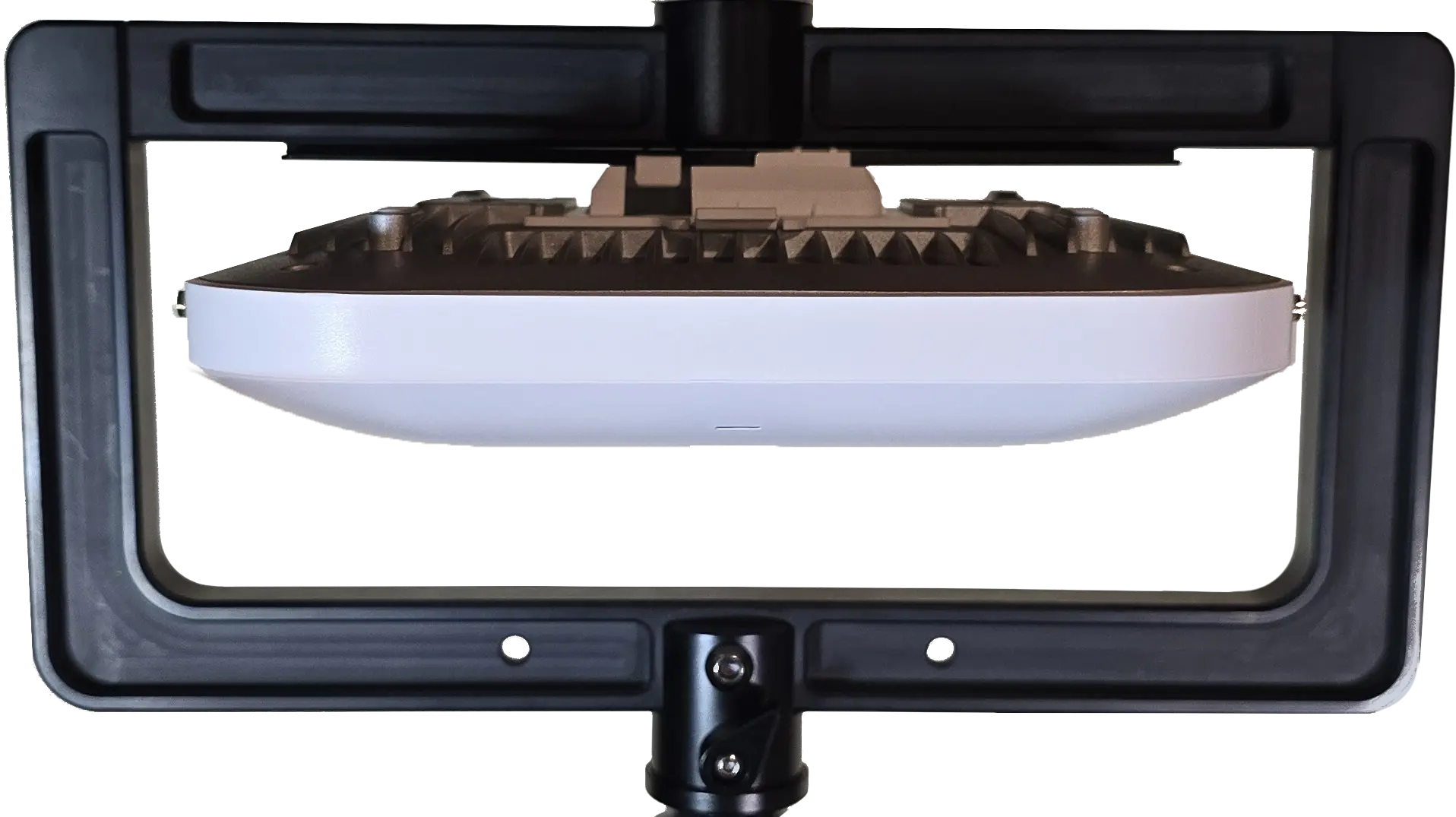
For Mako 5600 Gateway:
-
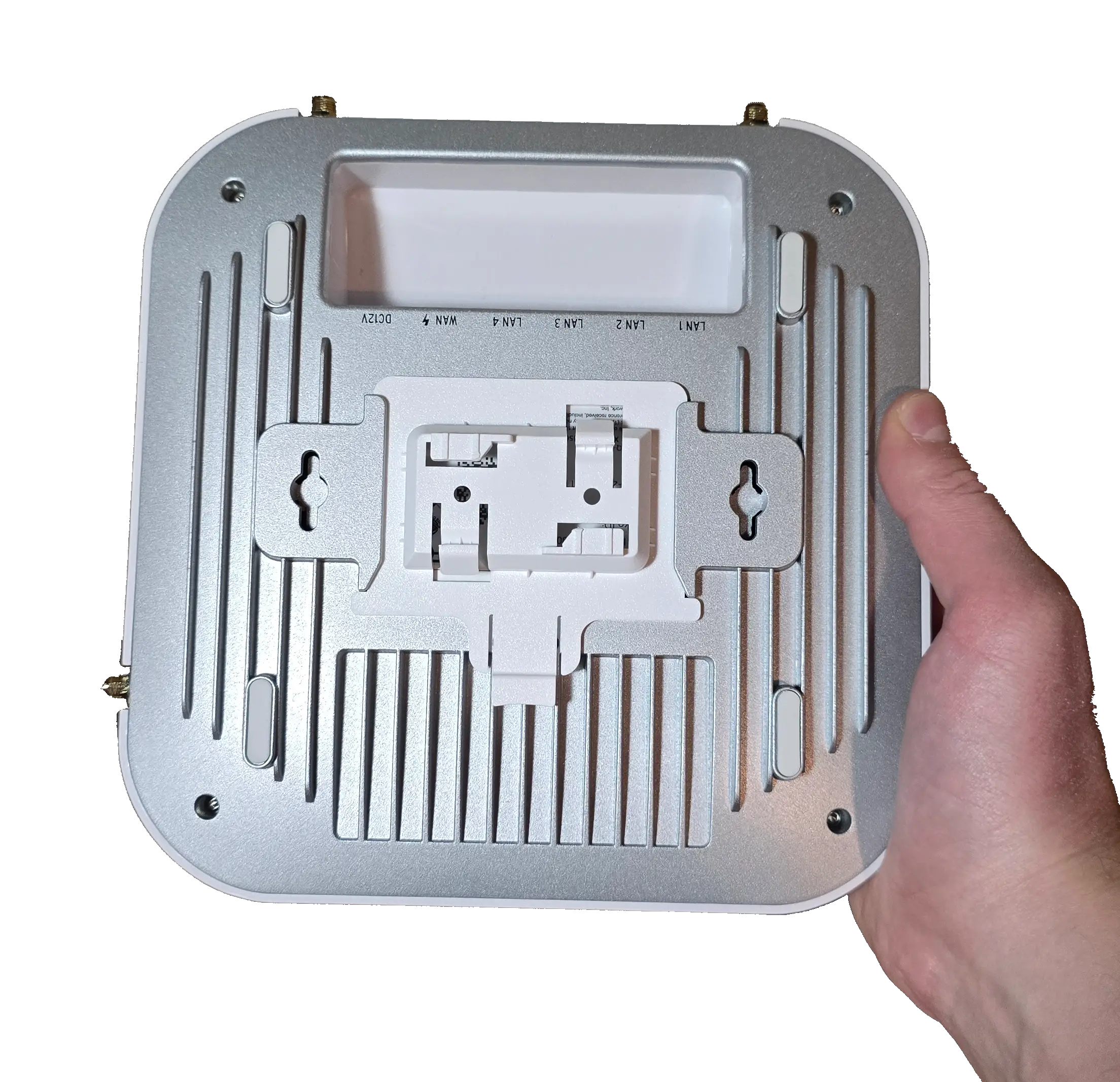
Attach the T-Bar Adapter to the Mako Gateway
- Provided by default and stored in accessory pouch
-
Mount the Mako Gateway to the Bracket
- Align and attach the gateway with the mounting bracket
- Make sure it is secured
-
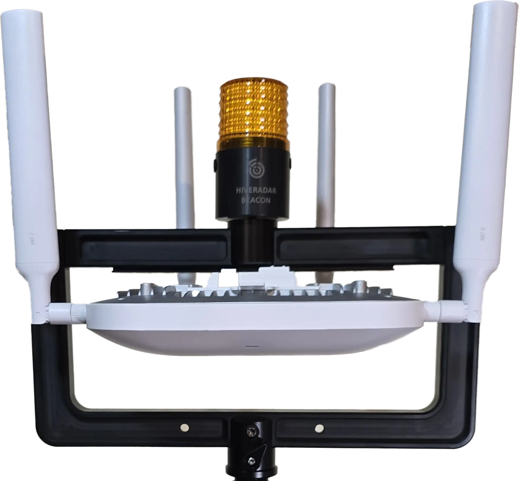
Install Antennas
- Install antennas by using the corresponding number on the antenna and the gateway port
For Other Gateways or Access Points:
-
Attach device-specific mounting bracket to T-Bar (if required)
-
Mount Your Gateway or AP to the Bracket
- Follow manufacturer mounting instructions
- Ensure secure attachment to T-Bar bracket
- Consider weight distribution

Optional: Install HiveRadar Beacon
The HiveRadar Beacon provides visual identification of the EDC location, especially useful in dark environments or crowded deployments.
Beacon Mounting Options:
The beacon can be mounted in two ways:
-
Directly on 3-section pole (no gateway/AP deployed)
- Screw beacon directly onto top of 3-section pole
- No T-Bar bracket needed
- Simplest option for beacon-only deployments
-
On T-Bar bracket (with or without gateway/AP)
- Mount beacon using screw mount on T-Bar bracket
- Can mount beacon + gateway/AP simultaneously (dual mounting)
- T-Bar has mounting rail on one side (for AP/gateway) and screw mount on opposite side (for beacon)
Note: The screw thread on top of the 3-section pole and the screw mount on the T-Bar bracket are the same width/compatible with the beacon.
Steps:
- Retrieve beacon from top storage shelf
- Choose mounting method:
- Option A (beacon only): Screw beacon directly onto top of 3-section pole
- Option B (with T-bar): Mount beacon using screw mount on T-Bar bracket
- If gateway is already mounted on the rail, beacon mounts on opposite side
- If no gateway, beacon can still mount on T-bar screw point
- Enable visual blinking (press button on side of beacon)
Step 5: Attach T-Bar to Pole
-
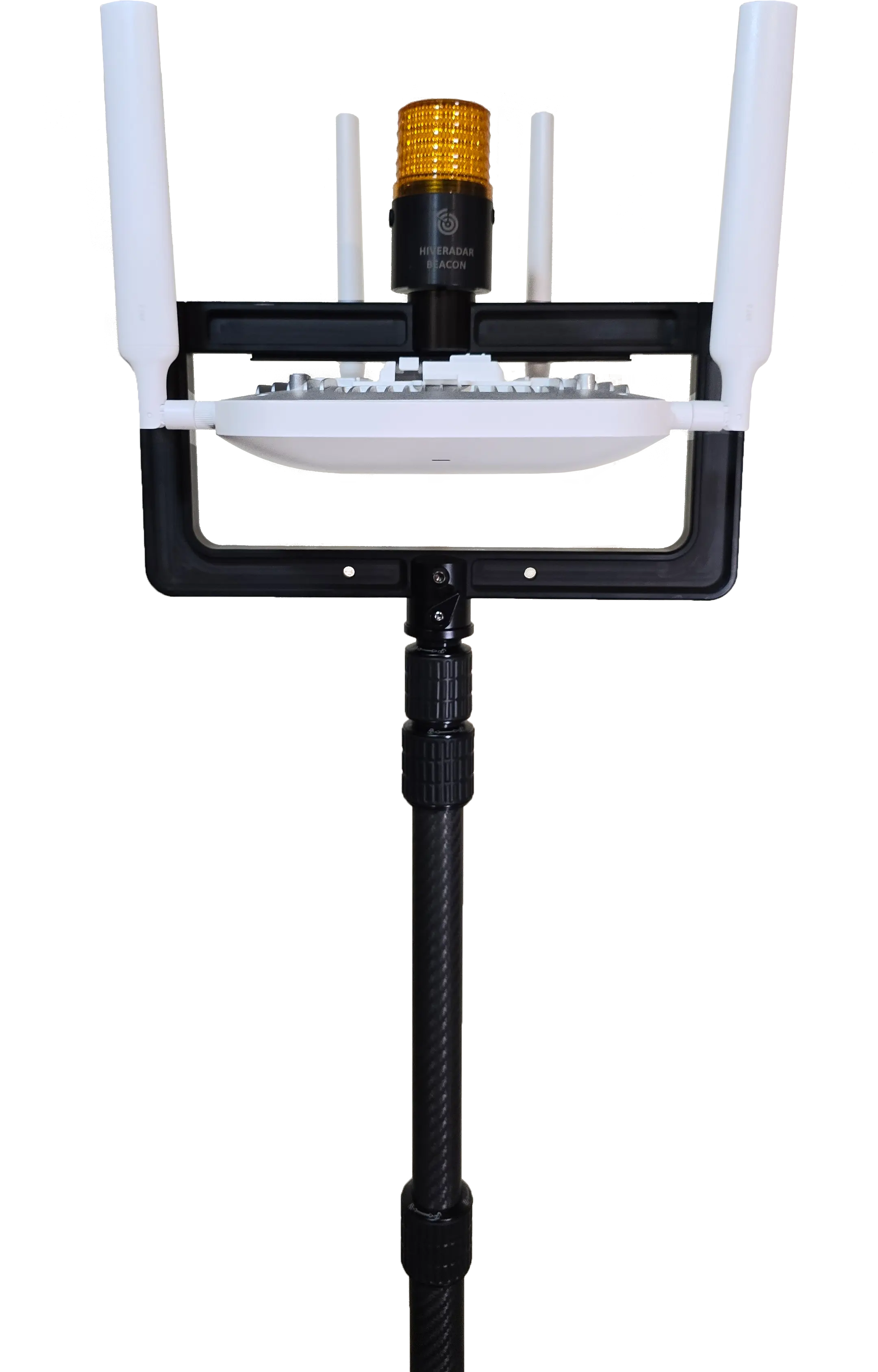
Position the T-Bar Bracket on the Carbon Fiber Pole
- Position the T-Bar bar mechanism onto the pole
-
Screw the T-Bar Clockwise Onto the Pole
- Do NOT fully tighten yet
- Leave slightly loose for orientation adjustment
-
Orient the T-Bar Bracket
- Loosen the orientation knob slightly (not fully)
- Rotate the T-Bar to desired angle
- Tighten the orientation knob to lock position
⚠️ Warning: Never over-loosen the orientation knob - it should only move slightly to allow rotation.
Step 6: Mount Pole to EDC
-
Check if Pole Needs Extension
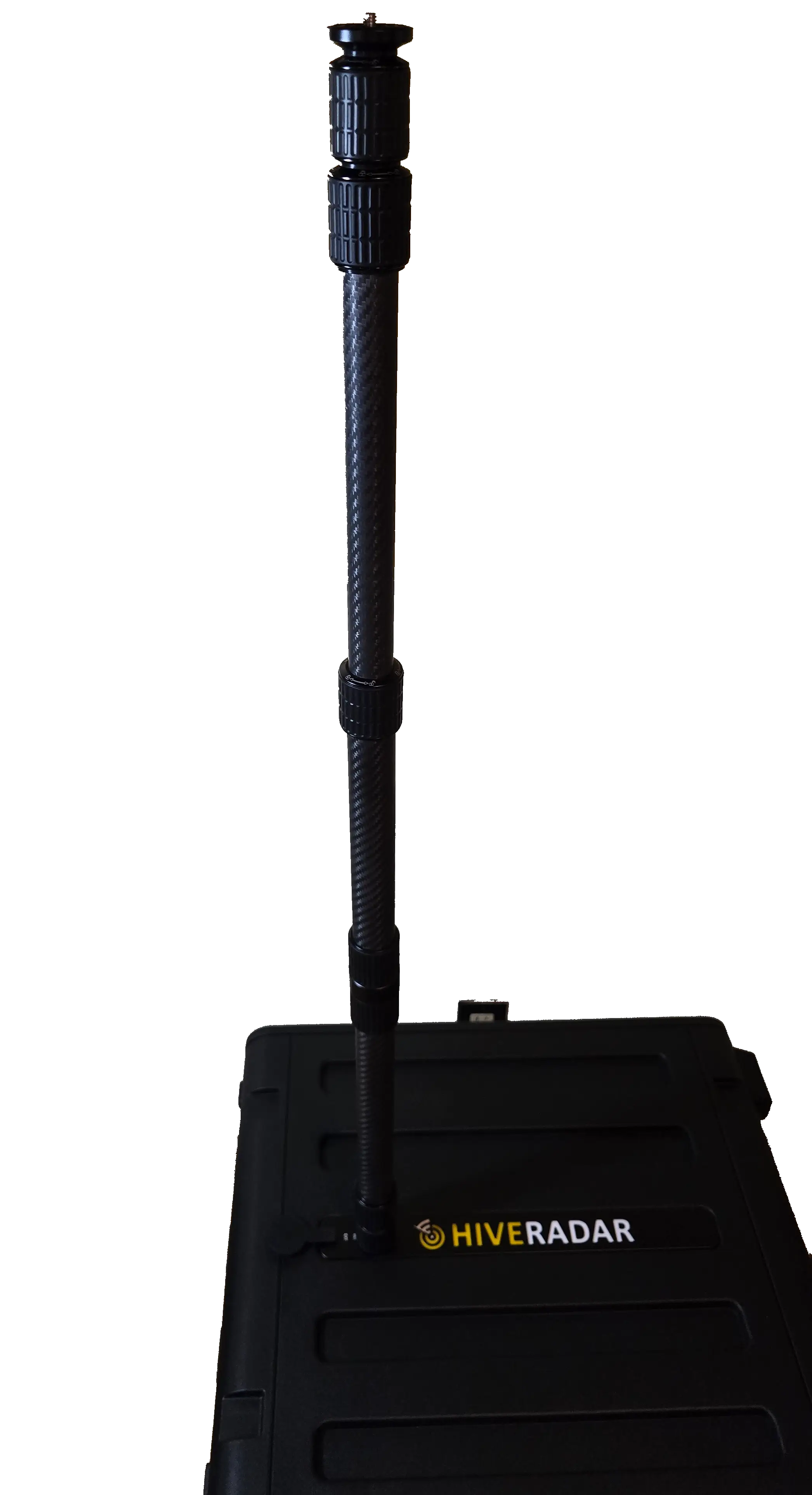
- You can either directly mount the 3 section telescopic pole or also use the carbon fiber pole extension that is stored in one of the lids
- If using only the 3 section pole, please make sure to extend the bottom section before attempting to screw the pole into the EDC
-
Screw the Pole Into the EDC Pole Mount
- Clockwise rotation
- If using extension pole, connect extension first, then mount to EDC
-
Tighten Securely
- Ensure pole is stable and secure
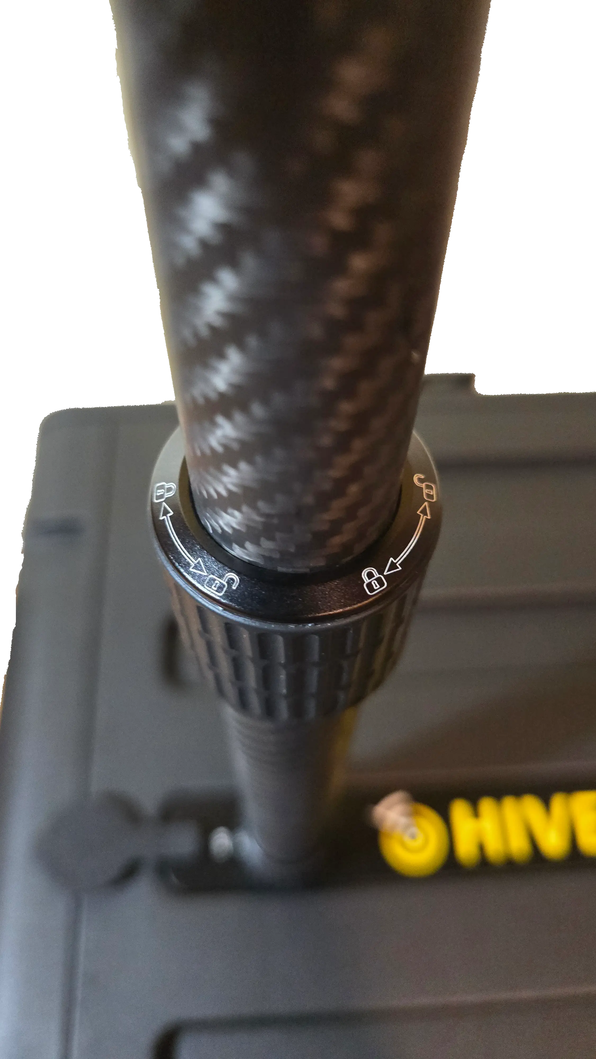
Image below is using the carbon fiber pole extension without the T-Bar bracket as an example of mounting the pole to the EDC hardcase with an extension pole.
Note: Lock/unlock symbols are printed on the pole itself for reference.
Step 7: Adjust Pole Height
- Extend the Telescopic Pole to Desired Height
- Follow the lock symbols on the poles
- Twist clockwise to unlock, extend/retract, twist counter-clockwise to lock
- Ensure all segments are locked before releasing
Step 8: Connect Cables
Connect Mako 5600 Gateway
NOTE: The instructions below show connecting Mako 5600 to the switch utilizing 2 ethernet cables, one for power (PoE) and one for data ingress from the Security Gateway. This is in cases where a PoE Splitter is unavailable.
It is recommened to use an included or after party PoE Splitter (12V 2A) to power the device due to complications with having to isolate traffic on the switch port that is powering the Security Gateway as it requires to be powered over its WAN port.
Cable Requirements:
- 2× Ethernet cables (included in EDC accessory kit)
- Connect Cables to the Mako Gateway
- Take the two Ethernet cables and plug them into the Mako Gateway:
- Connect the first cable to the WAN port
- Connect the second cable to the LAN port
- Take the two Ethernet cables and plug them into the Mako Gateway:
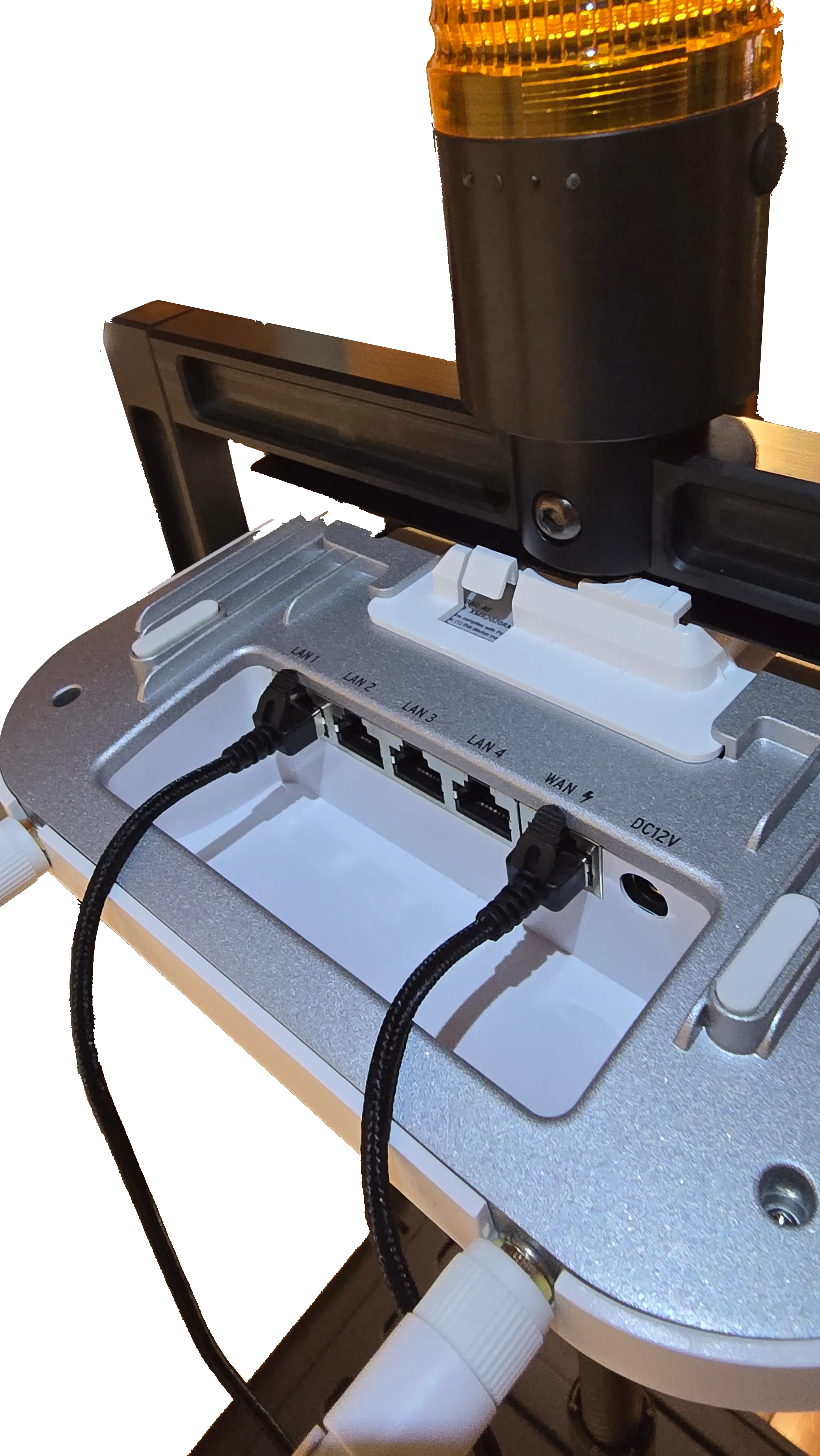
- Alternatively and recommended, a PoE Splitter can be used to power the AP instead by being directly connected to the DC12V Port and LAN1 Port.
-
Route and Secure Cables
- Route both cables down the pole towards the EDC
- Cable Management: Bundle the cables together using velcro straps; ensure the run is tight and looks neat (avoid loose hanging loops)
-
Connect Cables to the Switch
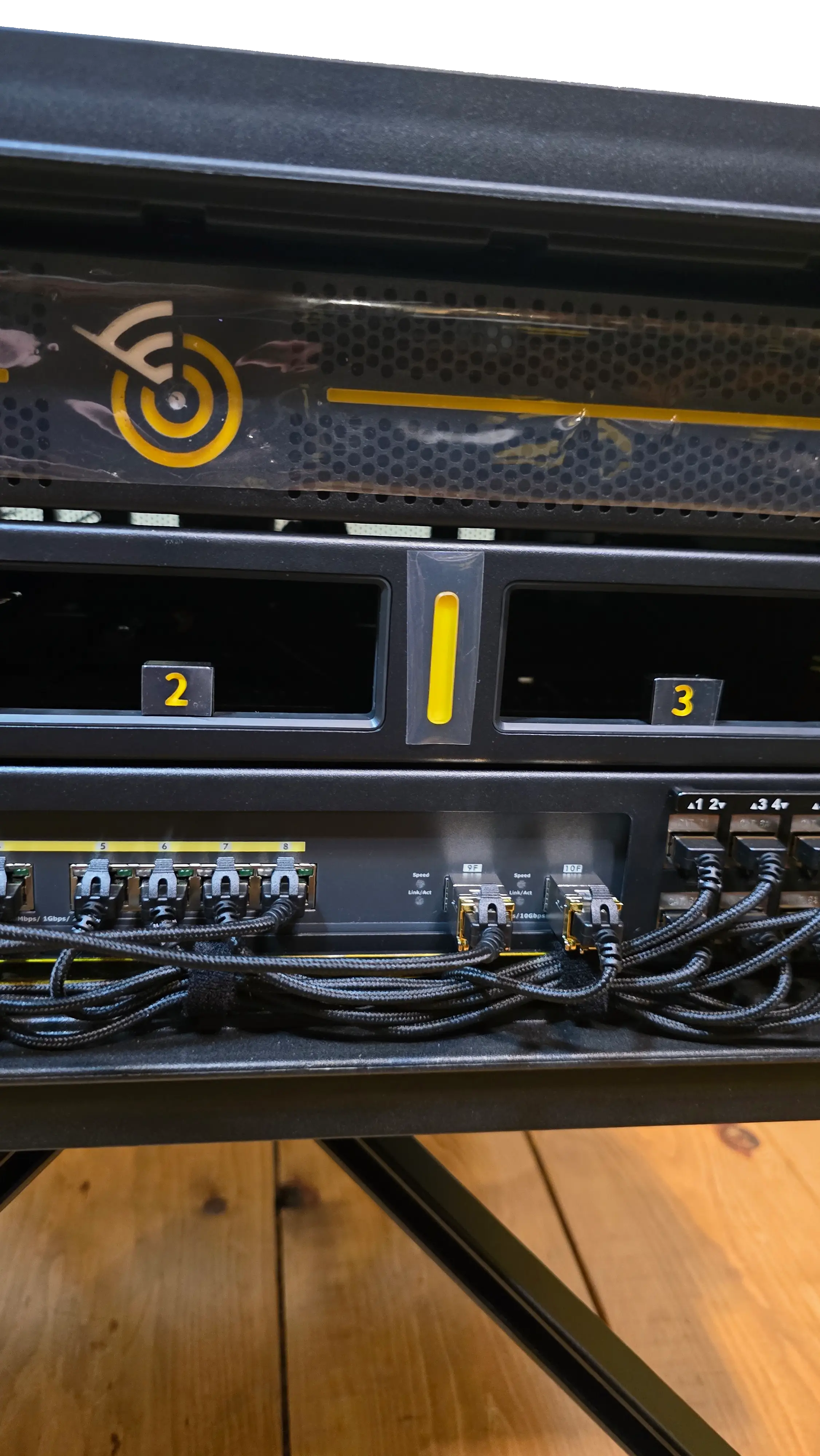
- Identify which cable corresponds to WAN and which to LAN, then connect them to the Switch:
- WAN Cable (Power): Connect to Switch Port 8 (RJ45 port)
- ⚠️ Important: This connection provides PoE power only. Network access on this port must be disabled or VLAN isolated (Mako limitation)
- LAN Cable (Data): Connect to Switch Port 10 (SFP+ copper transceiver)
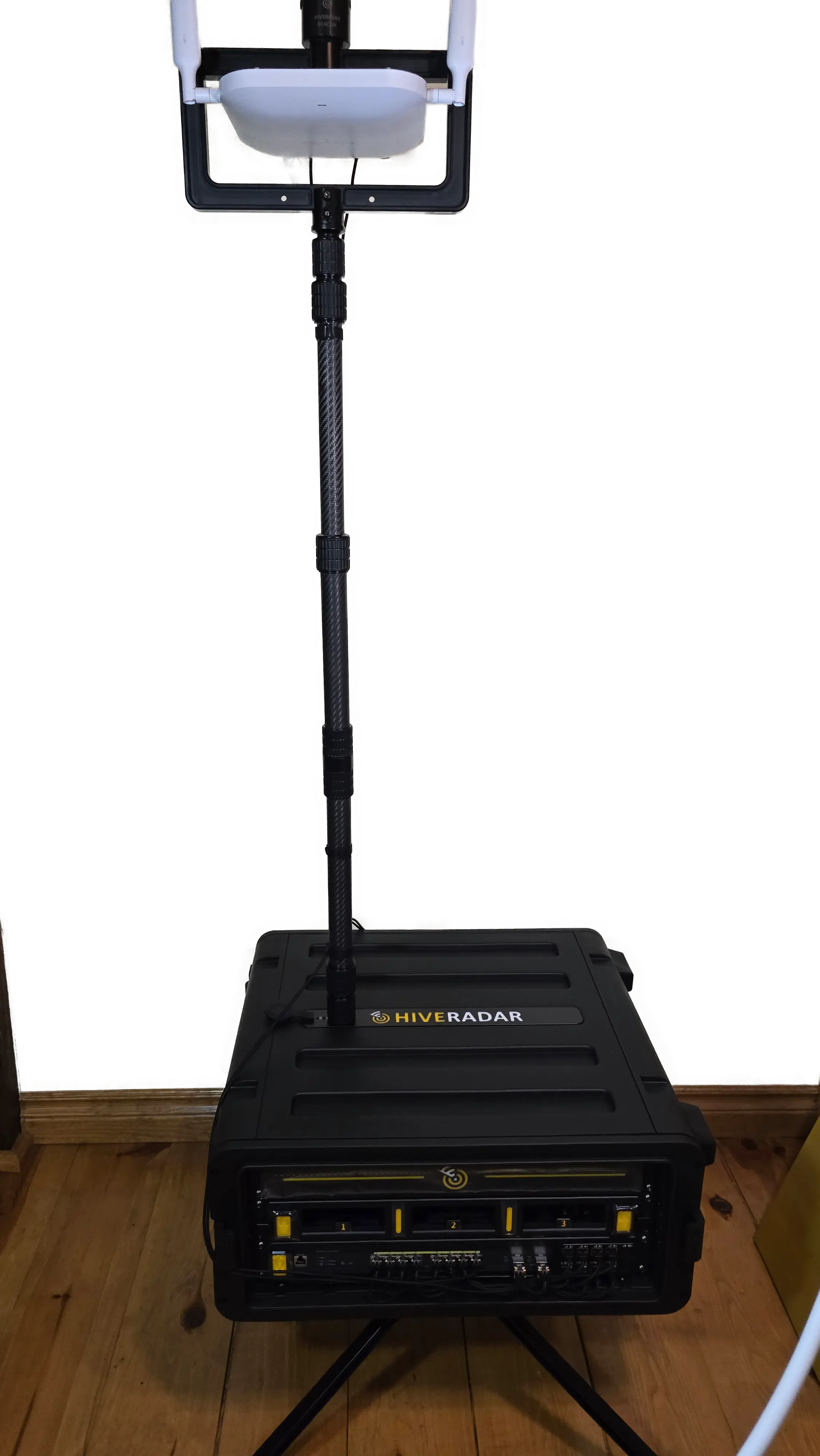
Fully Deployed:
For Other Gateways or Access Points:
Typical Configuration:
- Single Ethernet cable for data and PoE power
- Connect to available switch port (e.g., Port 8)
- Consult device documentation for port requirements
Cable Management:
- Route cables down the carbon fiber pole
- Leave slight slack at top to prevent strain
- Protect cables from pinching when retracting pole
Safety Notes
Pole Stability:
- Ensure pole is securely mounted before extending
- Do not extend pole in high winds
- Consider retracting pole during transport
T-Bar Orientation Knob:
- Never fully loosen the orientation knob
- Loosen only enough to allow rotation
- Over-loosening may cause parts to separate
Weight Considerations:
- Keep gateway weight reasonable
- Heavy equipment may affect stability
- Consider retracting pole in extreme weather
Cable Management:
- Secure cables along pole to prevent snagging
- Leave some slack for pole extension/retraction
- Protect cable connections from weather if deployed outdoors
Troubleshooting
Pole Won't Screw Into Mount:
- Check thread alignment
- Ensure rubber cover is fully removed
- Try slight rotation while applying pressure
- If using only the standard 3-section telescopic pole, make sure you have extended the bottom section before trying to mount
T-Bar Won't Stay Oriented:
- Tighten orientation knob more
- Check that knob hasn't been over-loosened
- Ensure T-Bar is properly seated on pole
Gateway Not Getting Power:
- Verify cable connected to correct switch port
- Check that port has PoE enabled on switch
- Verify switch is powered on
Disassembly and Storage
To Remove the Gateway and Pole:
- Disconnect cables from gateway
- Retract telescopic pole to shortest position
- Unscrew pole from EDC mount (counterclockwise)
- Remove gateway from T-Bar if desired
- Store Components:
- Carbon fiber pole → top drawer (use velcro strap to secure pole in drawer)
- Extension pole → work surface lid storage
- T-Bar bracket → top storage shelf
- Gateway and antennas → secure storage
- Re-seat rubber cover on pole mount
Additional Resources
For detailed mast specifications, weight capacity, troubleshooting, and maintenance:
👉 Telescoping Pole Reference Guide
What's Next?
After deploying the gateway:
👉 Positioning - Review clearance requirements with extended pole
👉 Component Locations - Reference guide for all EDC components
Continue to Part 4: Software Configuration for power and network setup.